Warning: VERY long read.
Looking over the production order form ,from the Studebaker National Museum, for the key code (part of the door lock project) we noticed the car was sold without a radio. We knew it did not HAVE a radio because there is a blank piece of chrome right there in the dash.
Of course that got us thinking and that is usually where the trouble starts. Do we need a radio, no. Do we need an AM only radio, no. Would it be cool to have a radio - even if it did not work, go on! And that's how it started. Maybe, just maybe, we could find an old radio in decent condition and clean it up. But it would have to be the right kind of radio right?? Per our usual we ran to Ebay and YES it was the right kind.
| Hover to see Ebay photos |
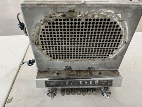 |
We would like to point out that we were very picky. We wanted one with preset buttons and the more the merrier. It was OK that it was broken. We just wanted it to look good and again, maybe, we could do something with it... (famous last words) We felt we could clean this up a bit and have a little fun.
What we saw when we opened it up was quite impressive. We had no idea what we were looking at but we knew most of it had to go.
| Hover to see the as found insides |
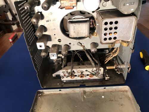 |
We stripped it down to just the mechanical parts which removed roughly 5½ pounds of "stuff". We were pleased that the when you depressed a button it would lock into place until you pressed another button. This was due to what we started calling a "latching bar" in the rear. Moving a button rearward raises the bar (which release any button already held) and then pushing a little further would allow the bar to drop into a slot locking in the button. At the same time the mechanism would move the indicator to a position behind the glass. This was cool and met every requirement we had - until we thought about it just a little more. Things like, "What if the radio lit up when you turned the power knob?" and "Wouldn't it be cool if button 3 was a 'hidden' cut out switch to the fuel pump?" See how much trouble thinking can get you?
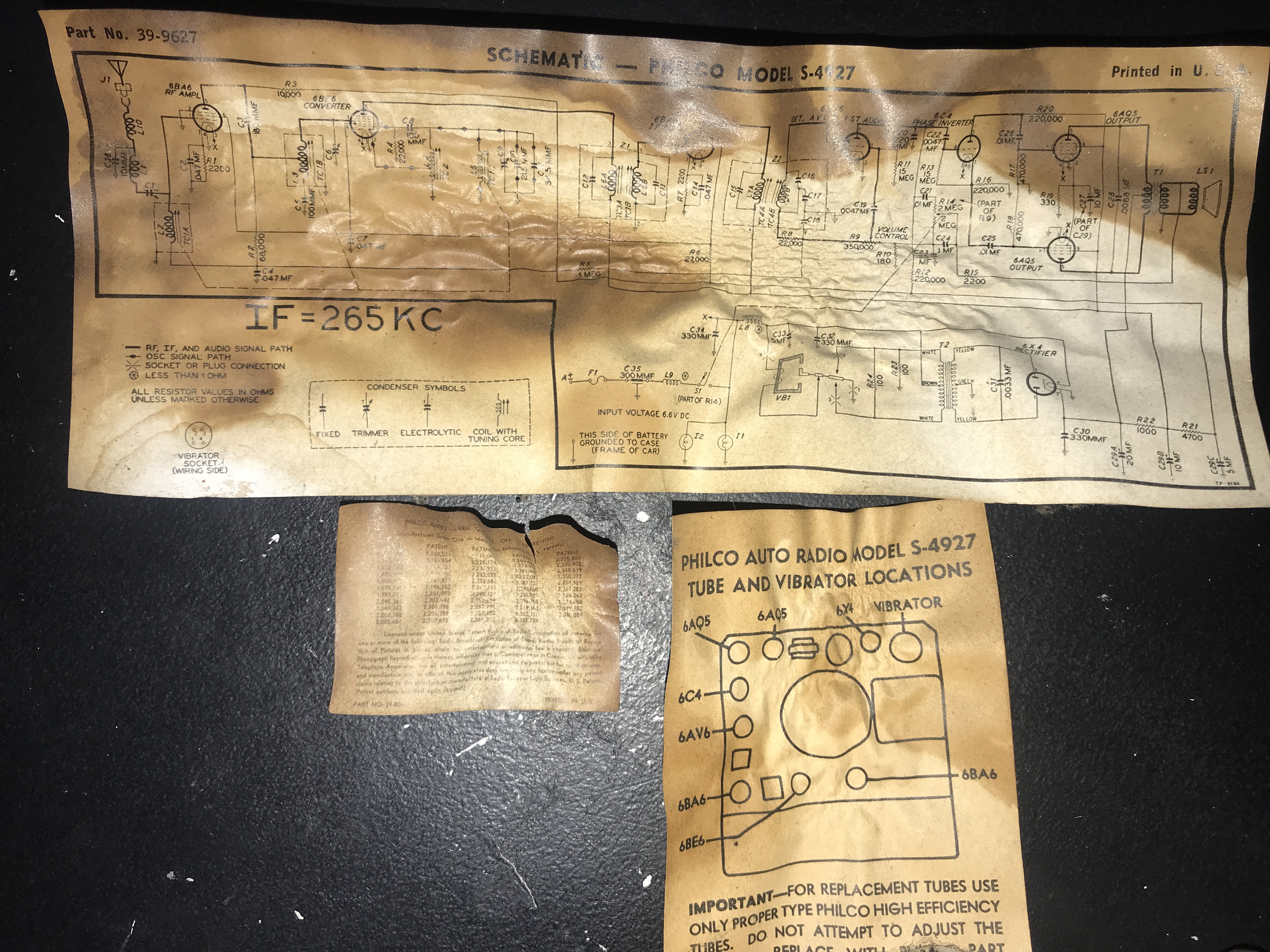
Sidenote: The following pieces of paper fell out of the radio when we opened it and we think there are just the coolest part of the purchase. Granted we have NO IDEA what any of this actually means but its cool none the less.
For our line of thinking we had a couple problems. First you can only push in one button and it stayed in place. This was just a matter of removing the latching bar, no problem. (this will haunt us later) Secondly; how to turn a purely mechanical sliding piece of Bakelite/steel into a switch? The short answer is you don't, or at least we don't. BUT, we did some more thinking and came up with a way to have the button push another button. :)
Taking this slowly we purchased some on/off SPST push button switches from Amazon. Granted we just learned enough to know that SPST means Single Pole Single Throw and the switches were fit for the power we hoped to run thru them. Using the last of the material from the Glovebox project we mocked up the SPST housing and what do you know - it worked.
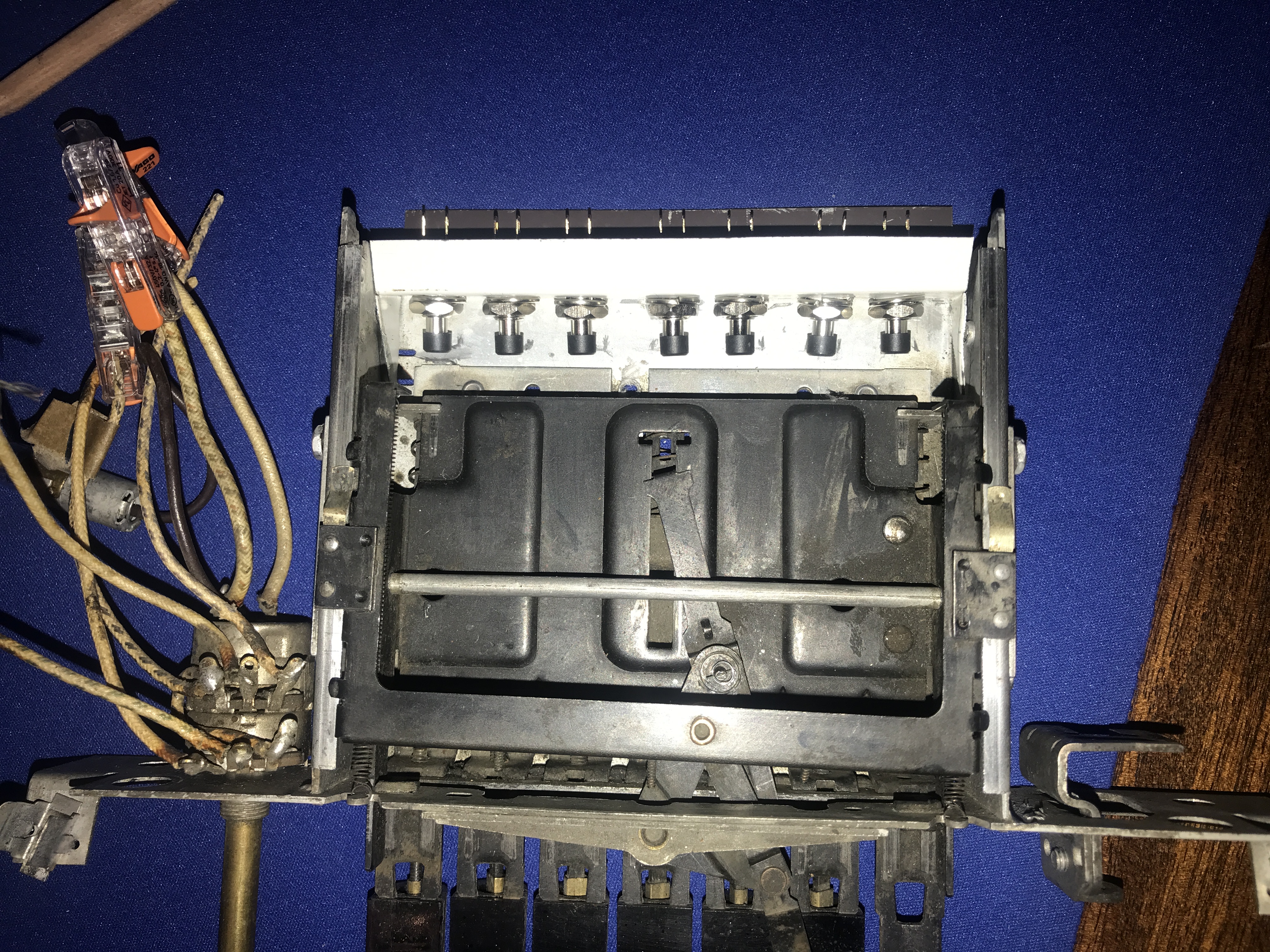
When you push a button it pushes a tab thru the center "carriage" (which manipulates the indicator) and a small tab comes out of the back. By positioning the SPST buttons in the right spot the tab pushes the button in and locks it or unlocks it depending on the previous setting. We now have Electo-Mechanical buttons. :) It was also in the moment we realized a problem. The latching bar was mounted in two pivot points at the top of the carriage rails (or at least that's what we called them) It also kept the rails from flexing in when you pushed the carriage and now it was binding. It took us 20 minutes to realize we could just put it back in but facing the wrong way. This keeps the rails from flexing BUT does not latch a button. Problem solved. We later cut it down a bit with a dremel.
This lead to us thinking about how to use all 7 buttons and the knobs if we could. The left most knob is the original on/off and the "Tone", and it worked on 6volts - hmmmmm. We realized we could step down the voltage and use this knob to trip a relay that would send power to the bluetooth speakers. (yes was part of the center console. We then realized that the right side knob could be a dimmer to the 6volt lights in the radio and we were off.
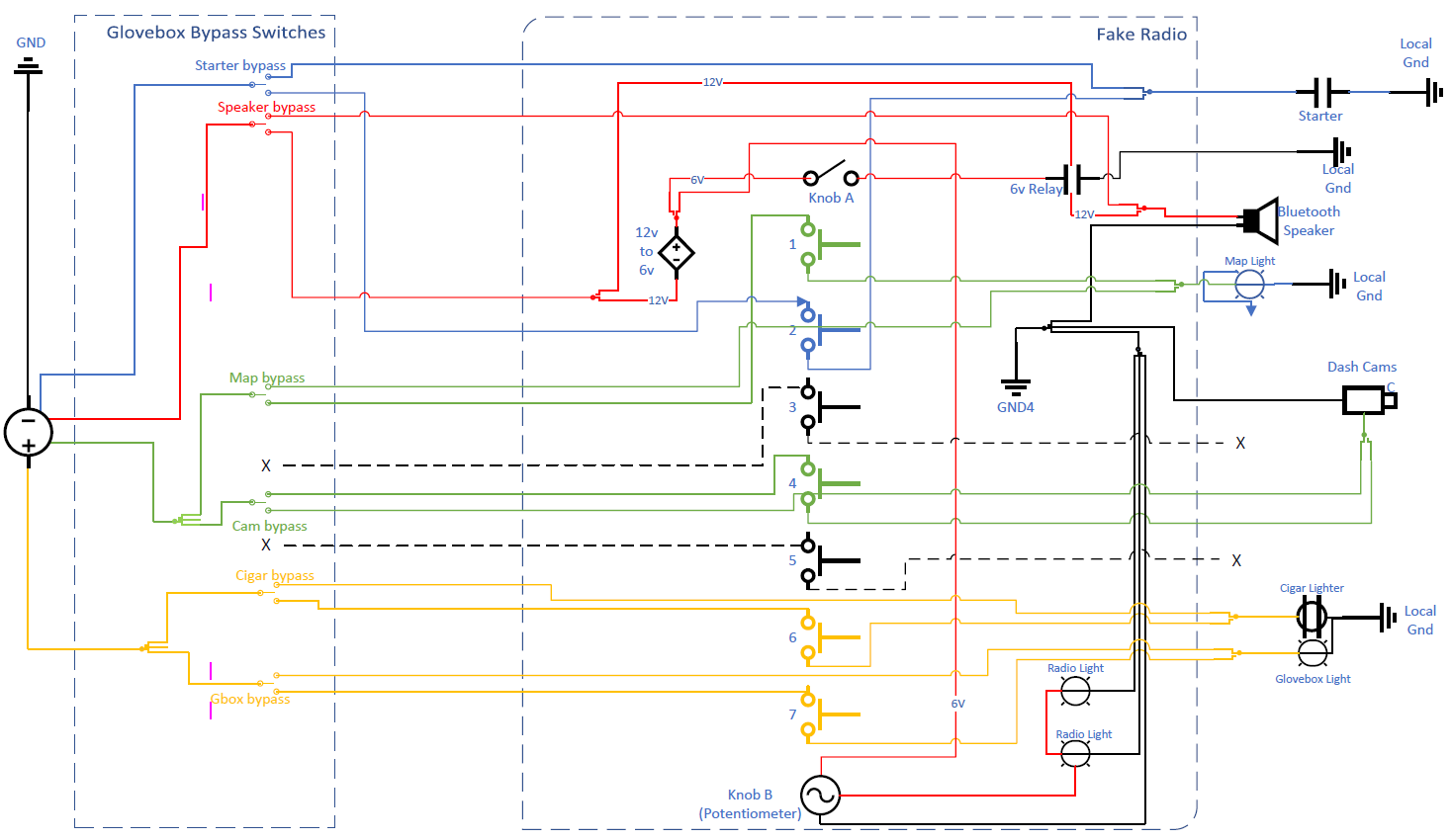
The discussion that followed turned into this:
Knob A = Radio lights and speaker power
Switch 1 = Map Light
Switch 2 = Neutral/Park Start Safety Switch
Switch 3 = null
Switch 4 = Dash Cams
Switch 5 = null
Switch 6 = Cigar Lighter
Switch 7 = Glove Box Light
Knob B = Radio light dimmer
| Click to view larger image | Click to use interactive version |
 |
|
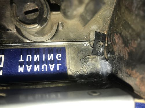
Along the way we discovered you can buy parts for Philco radios from yester year and AMAZINGLY found what we hoped would be replacement glass. Ours was OK'ish but would need to be either cleaned and restensiled or replaced. While we did not find an exact replacement for our part ID 54-5077 we did find part ID 54-5092 which was listed for a 51' model radio so we went for it. The actual description read: Dial glass for Philco S-5127 Auto Radio (51 Studebaker). Philco part # 54-5092. 9.28" W x .95" H x .094" thick (nominal) Did you catch the "nominal" bit ‽

At first glance it looked close but the numbers were a little more spread out. No big deal to us as this was just decoration. When we attempting to install the glass we found it was just a little to tall (width)... $%^& Risking our $46 investment ($35 plus S&H) we went to the dremel tool and removed just enough of the corners to MAKE IT FIT! (Silicone added to remove any vibration rattle.)
| Hover for Dremel Hacking |
 |
We now needed to learn how to solder. Oh you read that right, our solder skills are just about zero. We watched some YouTube videos to figure out the basics and started the process. Did you know temperature is important? That putting WAY to much heat into say a small SPST switch would melt out the plastic and ruin the switch. Well we do now. Ultimately we got there, that and a bunch of cleaning happened.
| Hover for Before/After soldering |
 |
We decided that removing the buttons made more sense and made the soldering was much easier. Naturally when we tried to reinstall the switches we broke some of the connections so it was a bit of back and forth. In the end each switch tested fine and we carried on.
You may have notice we installed a potentiometer (pot) behind Knob B. This works as a voltage splitter and thus becomes the dimmer to the radio lights. You may also have noticed that it is NOWHERE near the knob. We just needed something that could connect the two. Something that could be modified into a thin piece with tabs on each end. Casting around we found the copper tubing from the Fuel Fill project. (this was to make the vent line) With a very short section we straightened it (cool process involving a vice, vice grips, and a hammer) and then flattened the ends to make the tabs. With a simple bracket to hold the pot if is just a simple step to slot in the ends and Bob's your uncle.
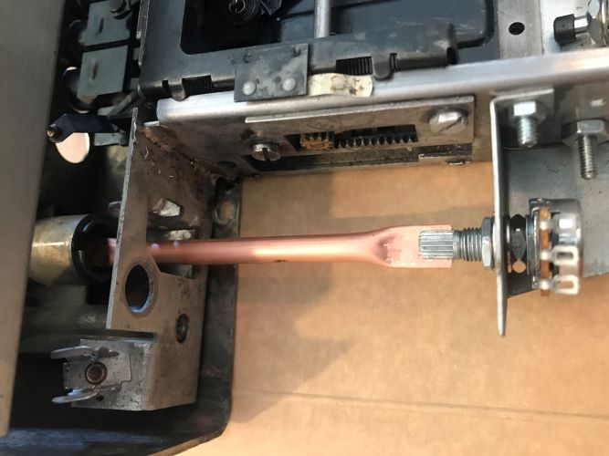
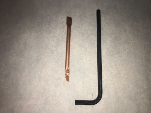
While the above picture may look nice we found an issue with the strength of the copper. You could, quite easily, over torque the stops of the pot and twist the copper. This would not do at all. Looking around in the garage we found that bin that we all have. The one with the over sized Allen Wrenches (Hex Keys?) that one saved because "someday..." Well we finally found that day!
| Hover for Before/After Hex Key Mod |
 |
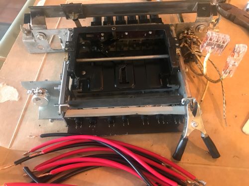
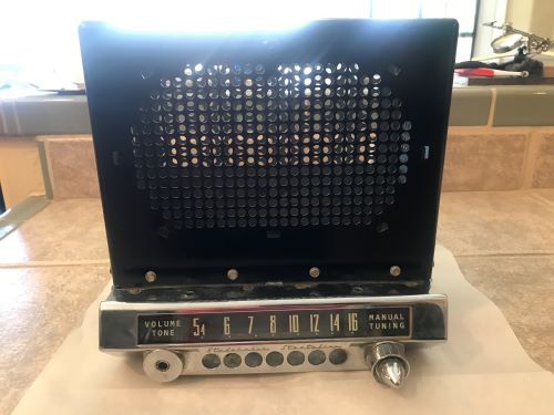
We needed to figure out where to port all of the wires through the case and this meant fitting the unit under the dash. If there was no room behind the unit we could install them high up on the side OR we considered cutting down the unit now that all of the electronics were gone. Fitting the unit involved removal of not only the blank but the entire center console. yuck! Here is what the unit looked like for this mock up after some agressive cleaning and gloss black paint. Note: we did not need to paint all of it but this way we did not need to figure our that would be seen and what would not.
| Hover for different view |
 |
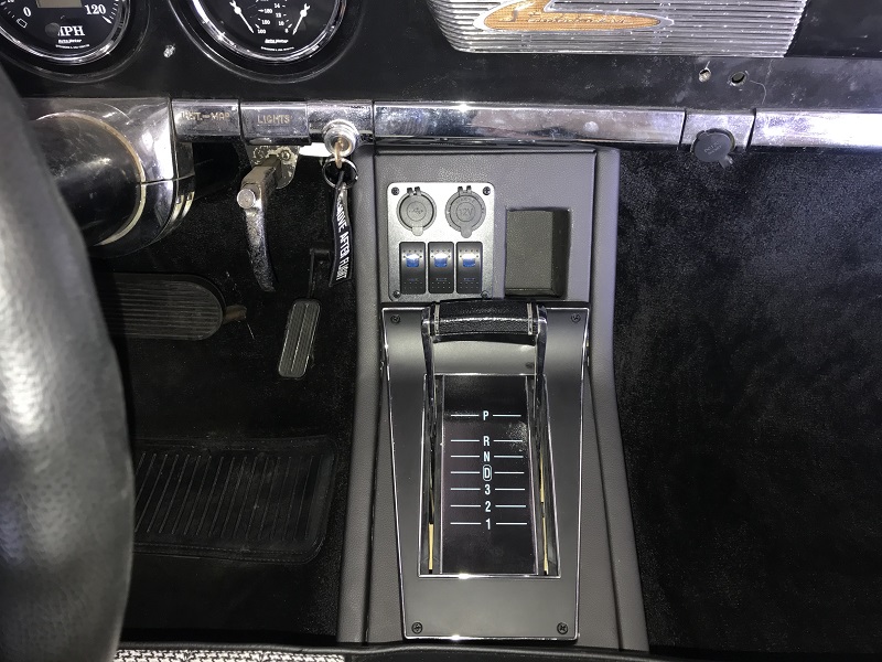
During the construction phase we found a replacement glovebox door. We have one but it was painted black, by The Previous Owner (love that guy), while this one is polished stainless, AKA original condition. We also took a moment to update the console. Not only removing the now abandoned switches from the Center Console Project but enlarging the "cubby hole" and adding a bit of houndstooth as one tends to do!
The following slideshow shows the installation steps in the ChevyBaker!
During all of the wiring part of the project we determined the glove box light needed updating. You can see this update in the Glove Box Light page.
So in the end it looks cool, provides a bit of security (starter lockout), and hides some of the more custom controls (Blue Tooth Speakers and Dash Cameras).
The best part is reaching over and turning "on the radio" to turn on the bluetooth speakers which then automatically connect to an iPhone.
If the iPhone just happens to be playing VAN HALEN so be it...
| Here is the parts/price list for this project: | |
| Original Radio | $122 |
| 12V/6V transformer | $9 |
| SPST Switches | $20 |
| On/Off/On switches | $24 |
| WAGO single connectors (for testing) | $15 |
| WAGO 3-way connectors (for testing) | $8 |
| WAGO 5-way connectors (for testing) | $9 |
| Potentiometers | $7 |
| Dial Glass | $46 |
| Relay | $12 |
| Wiring | $0 |
| Misc. Connectors | $0 |
| Paint/Primer | $0 |
| Total | $272 |
As always, thank you for your time in reading this.