Electronics
At this point we have cameras that have BNC connectors, powered by 2.5mm DC, and we need to bring ALL of this to a central point. Once gathered we need to get power to the table and the video signals off the table to a recorder which we have not purchased yet but have done basic Internet research.
It was decided to use Cat5 network cable for the video camera feeds. Because Cat5 has 4 pairs (8 wires) we can get 4 cameras per cable and allows us to transfer the feeds thru a keystone plate between positions 1 and 9. Internally seats 2 to 5 use one cable, seats 6 to 9 use a second cable. Seat one, which we considered heavily, uses a third cable all by itself. The heavy consideration was due to the cost difference between an 8 camera and a 16 camera recording system.
The power to each camera was made from 2-wire doorbell wire. This provided the proper gauge needed and was cheap. We simply cut the required length to each camera and then wire tied them into a make shift wiring harness. Like the Cat5 network cable - cameras 2 to 5 and 6 to 9 are wire harnessed with camera 1 being seperate.
So, now we have wire for power and video to each camera but how to connect to the camera? UTP BALUN A balun allows traditional coax cable to be replaced by category 5 and other forms of twisted pair wire in CCTV video camera & surveillance installations. Thats right, we are basically building a CCTV camera system. By adding a BNC balun to the camera video output we attach the network pair to the balun. Using the Cat5 was great as each camera uses a coloured pair (such as the Brown Brown/White pair shown below) We then add a DC power balun to the power lead of the camera and wired it with the doorbell wire harness. At each block location we used shrink wrap to protect the wiring. This may have been overkill but we where already deep into the build and wanted to protect against any issues.
In this image we see seat 6, which is at the end of the power harness and cat5 cable, with the baluns attached. The foam tape strips were used to keep the wiring positioned. This foam was needed in a later step and the excess was used here. You can also see how the camera is attached to the mounting bracket which was first attached to the block. The tolerances here were very tight. We could not attach the bracket to the camera first because then there was no room to attach the bracket to the block. We also did not use washers on the nut side of the block allowing the nut to be "sucked into" to wood which then ensures the nut will not back off.
We also standardized the color coding for all of network and power wiring. All negative terminals use the "white" wire in the color wire pairs. Example: Camera 6 uses the Blue and Blue/White network cable wires for the video. The blue/white wire is the negative wire. Likewise the red/white wire on the power harness is used for the negative side of the DC power balun.
With each camera now connected to the power and video wiring harnesses it was time to address the connection point. Baluns were added to the end of power harness pairs and each cat5 pluged into the keystone connectors mounted into a shaved down wall plate. A word on the power system. We used a 10amp power supply with an extension to the table. A 2:1 splitter protrudes through a keystone blank (with a hole drilled in it to match the diameter and a slot cut to insert the splitter wire). Each side of the 2 way spliter is then split again using a 5:1 splitter making 10 power leads. 9 leads are then plugged into the power baluns with the 10th lead powering the LED light. All power baluns were shrink wrapped to their mating partners to ensure they will remain connected. We also made a "spreader plate" for the power baluns to ensure that no two baluns could touch their contact points. (screws) This was made from excess plastic from the camera track covering. As you can see this makes a very congested area behind the keystone plate and why we added the block near camera 9.
You can see we added a strip of black foam (weather trim) to the inside edge of the inner covering. We first attached the foam strip to the top of each support block next to the inner covering. We then attached a second strip to the inner edge of the first strip to create a "gasket" that would be sandwiched between the inner covering and the padded rails once it was reattached. This was needed because when we cut the camera track oval, and then decided to make it 3 inch wide, we messed up. During a "fit test" we discovered small gaps where the inner plastic covering did not fit well enough to hide the "magic". The following image shows the wiring connection point between seats 1 and 9 and the first foam strip.
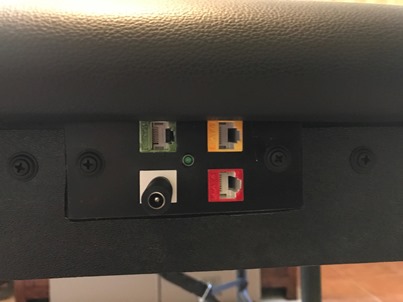
Using the same plastic as the inner covering we wrapped the exterior of the camera track. The following image shows the tables keystone plate with the 3 network cable keystones, the power plug, and the power LED. Moving the LED ot the center was a bit of a trick as the corners of the keystone connectors has to be shaved. In the end there was just enough room to drop the nut straight down betwen them and use twizzers to turn it in place.
We condidered many options to make the power connector flush in the wall plate but in the end decided that the plug does not extend past the edge of the padded rail and being lazy was the final option. We also placed the cut in the keystone blank on the bottom edge to hide this from the casual viewer.
The 3 network plugs are colour coded (thank you to my daughter for the fingernail polish) making the setup more of a plug and play activity, more on this later)
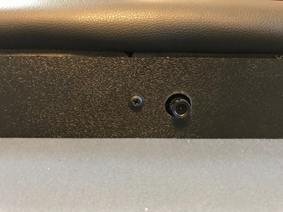
Each camera blends in pretty well we believe. Each camera location also received a single screw that holds the inner covering in place. The screws used to hold the plastic covering were unique as they have a small decorative washer attached. Oddly, these were found at an automotive store. We considered using velcro but felt that it would be insecure.
Now its time to mount the padded rail. This was originally done from the bottom side of the play surface, with 1.5 inch bolts, into tee nuts mounted in the padded rail. (we may post our initial table build later) The original bolts were replaced with 4 inch bolts. Remember the camera track is 2.5 inch tall? 4 - 1.5 = 2.5 :)
The original bolts were put in a zip lock bag and using excess foam strips (ya we had a lot left over) stored inside the camera track between seats 5 and 6. Think about this for a moment. All of the wires to seat 5 come clockwise and all of the wires to seat 6 come counter clockwise. This left a great area to store the original bolts. We now have the option to remove the camera track and using the original bolts reattach the rail thus reverting the table back to its original state.

